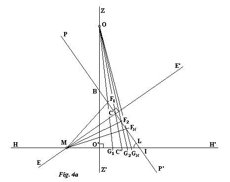
From any point B on the polar axis PP', drop the vertical ZZ' perpendicular to HH' at O'. Z is chosen on the side of point C opposite the horizon HH' and represents the zenith. In order to locate the center O of projection, from the point B as the center, lay out the distance MB on the axis ZZ', either towards the top in the direction of Z or towards the base. In this last case, the center of rotation of the style will be situated under the dial. Selecting O on ZZ' so that OB = MB will yield a dial whose hour points lie on a circle.

From the point M and making the angle of the sun's declination for different dates with the straight line segment MC, trace the straight line segments MF1, MF2, etc..., the angles being counted positive in the direction of P. From the point O draw the straight lines OF1, OF2, etc... that cut the horizon HH' in G1, G2, etc... These points correspond to the foot of the style for the different chosen dates. Thus, to locate the foot of the style for the equinoxes, draw the straight line segment OC to obtain the required point C'.
There are two methods for finding the center of the projected circle on the straight line HH' (Fig. 4b). The first consists of laying out the distance CM, on the other side of C along the straight line EE', in order to obtain the point N. From O, draw the straight line segment ON that cuts the horizon HH' in N'. The center J is then found in the middle of the segment MN'.
The second method results directly in the point J. Trace the straight line MB; then from M draw the perpendicular to this line that cuts the axis PP' in T. The straight line that joins the points O and T then cuts the horizon HH' in the center J.

Referring back to the straight line HH', we place ourselves in the plane of the horizon and of the dial and then trace the projected circle with center J and radius JM. In order to graduate the circle in hours, trace the straight line DD' perpendicular to HH' through point M. Using a compass with M as a center, mark off a distance equal to MC on the straight line HH' to obtain the point K (i.e. KM=MC). From K, draw ten straight line segments to DD' at 15° intervals from HH' in order to obtain the intersections Q1, Q2, etc...From these points, trace straight lines passing through C'; they each cut the projected circle in two points, yielding two new hour graduations. To obtain the graduations of 6 and 18 hours it is necessary to trace the perpendicular to HH' passing through C'. The numbering is then done in order from point M that corresponds to 12 hours, recalling that the hours of the afternoon are always to the east of the meridian line HH'.
If the drawing was not placed on the meridian line, place it there now, with HH' on the meridian and with H to the north. It is then necessary to fix the center of rotation of the style in the meridian plane, to the vertical from point O' and distant from this last by a length OO', below or above the dial. In the latter case, one can produce a style sliding across the axis of rotation in a way to be able to position its extremity on the different marks whatever the season.
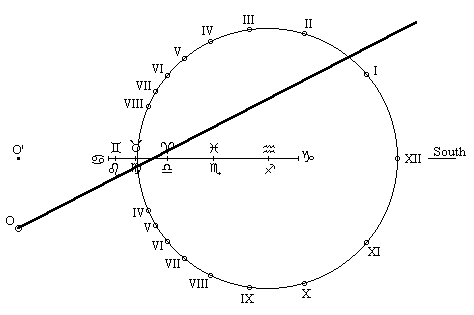
Let's finish finally by presenting some drawings using the zodiac calendar. They were executed for the latitude of 49° north with the axis of rotation of the style above or below the dial and for various values of the angle CMB.
Axis of rotation above the dial
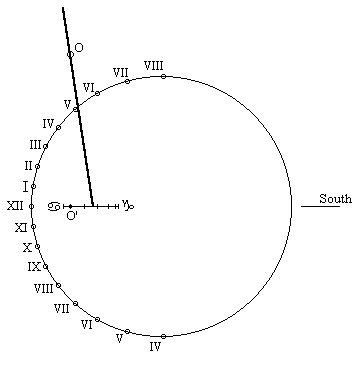
Axis of rotation above the dial
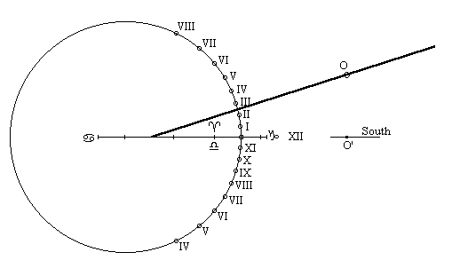
Axis of rotation below the dial
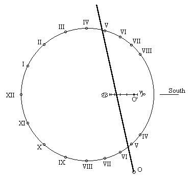
Axis of rotation below the dial
Date written: 31 August 97
Date translated: 4 February 98